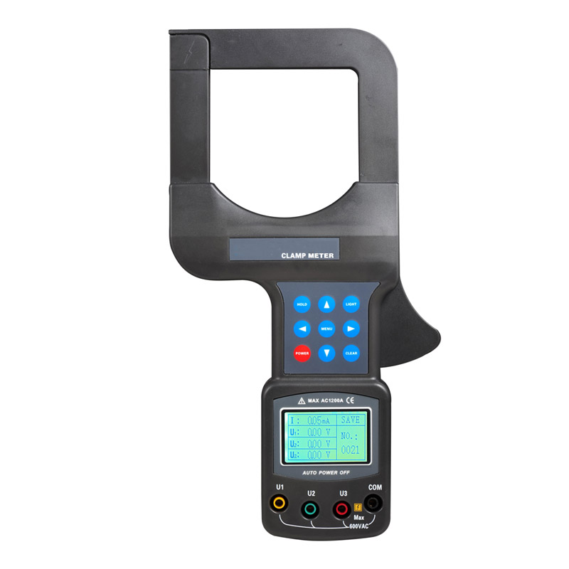

Three phase harmonic power quality analyzer with CT
1. Test function
★ Waveform real-time display (4 channels voltage/4 channels current).
★ True RMS values of voltages and currents.
★ The DC components of voltages.
★ Peak current and voltage values.
★ Minimum and maximum half-cycle RMS current and voltage values.
★ Pharos diagram display.
★ Measurement of each harmonic up to order 50.
★ Bar charts show harmonic ratios of current and voltage of each phase.
★ Total harmonic distortion (THD).
★ Active, reactive, apparent power, by phase and cumulative.
★ Active, reactive, apparent energy, by phase and cumulative.
★ Transformer K factor.
★ Power factors (PF) and displacement factors (DPF or COSΦ).
★ Short-term voltage flicker (PST).
★ Three phase unbalance(current and voltage).
2. Transientcapture function
Monitoring instantaneous change of power grid voltage current parameters, including the voltage current fluctuations, voltage
current surge, sag and short supply interruption, temporary overvoltage, impact current and Current voltage instantaneous
distortion. Instruments can store 150 sets of transient waveform at the same time.
Can be display the RMS rising / falling curve In the startup process, the envelope curve of startup current, waveform of 4
channels current and 4 channels voltage. Recording about 100s after trigger, storage the current /voltage instantaneous and
waveform curve of each cycle in 100s.
Aunb, KF,W, VAR, VA, PF, COSφ, TANφ),50 voltage harmonics, 50 current harmonics. And create the trend curve. Record data for a
long time according to need(concurrent selection 20 parameters to record data for once every five seconds, you can record about 300 days.).
voltage, current, unbalance, harmonic ratio, frequency, active power, total harmonic distortion. You can configure 40 different
alarms, each group can set different monitoring parameters (including 50 harmonics, total of 123 different parameters) and limit
values, also can set the shortest time of overshoot. The log can contain up to 12,800 alarms.
and current waveform, harmonic bar chart, phasor diagram etc. It can save a maximum of 60 screen snapshot.
waveform, trend chart recording, alarm log, screenshots, and display on the computer.
curve colors’.
Choice of type of connection to the net work.
Configuration of the type of the current sensors and voltage ratios.
Select Chinese menu or English menu.
|
Measurement
|
Range
|
Display resolution
|
The maximum error in the range of the reference
|
|
Frequency
|
40Hz~ 70Hz
|
0.01Hz
|
±(0.03)Hz
|
|
True RMS phase-to-neutral voltage
|
1.0V~ 1000V
|
Min resolution 0.1V
|
±(0.5%+5dgt)
|
|
True RMS phase-to phase voltage
|
1.0V~ 2000V
|
Min resolution 0.1V
|
±(0.5%+5dgt)
|
|
DC voltage
|
1.0V~ 1000V
|
Min resolution 0.1V
|
±(1.0%+5dgt)
|
|
True RMS current
|
10mA~ 6000A
|
Min resolution 1mA
|
±(0.5%+5dgt)
|
|
Peak of phase-to-neutral voltage
|
1.0V~ 1414V
|
Min resolution 0.1V
|
±(1.0%+5dgt)
|
|
Peak of phase-to-phase voltage
|
1.0V~ 2828V
|
Min resolution 0.1V
|
±(1.0%+5dgt)
|
|
Current peak
|
10mA~ 8484A
|
Min resolution 1mA
|
±(1.0%+5dgt)
|
|
Peak factor
|
1.00~ 3.99
|
0.01
|
±(1%+2dgt)
|
|
4.00~ 9.99
|
0.01
|
±(5%+2dgt)
|
|
|
Active power
|
0.000W~ 9999.9kW
|
Min resolution 0.001W
|
±(1%+3dgt)
Cosφ≥0.8 |
|
±(1.5%+10dgt)
0.2≤Cosφ<0.8 |
|||
|
Reactive power, inductive or capacitive
|
0.000VAR~
9999.9kVAR |
Min resolution 0.001VAR
|
±(1%+3dgt)
Sinφ≥0.5 |
|
±(1.5%+10dgt)
0.2≤Sinφ<0.5 |
|||
|
Apparent power
|
0.000VA~
9999.9kVA |
Min resolution 0.001VA
|
±(1%+3dgt)
|
|
Power factor
|
-1.000~ 1.000
|
0.001
|
±(1.5%+3dgt)
Cosφ≥0.5 |
|
±(1.5%+10dgt)
0.2≤Cosφ<0.5 |
|||
|
Active energy
|
0.000Wh~ 9999.9MWh
|
Min resolution 0.001Wh
|
±(1%+3dgt)
Cosφ≥0.8 |
|
±(1.5%+10dgt)
0.2≤Cosφ<0.8 |
|||
|
Reactive energy, inductive or capacitive
|
0.000VARh~ 9999.9MVARh
|
Min resolution 0.001VARh
|
±(1%+3dgt)
Sinφ≥0.5 |
|
±(1.5%+10dgt)
0.2≤Sinφ<0.5 |
|||
|
Papparent energy
|
0.000VAh~ 9999.9MVAh
|
Min resolution 0.001VAh
|
±(1%+3dgt)
|
|
Phase angle
|
-179°~ 180°
|
1°
|
±(2°)
|
|
Tanφ
(VA≥50VA) |
-32.76~ 32.76
|
Min resolution 0.001
|
φ:±(1°)
|
|
Phase shift of power factor (DPF)
|
-1.000~ 1.000
|
0.001
|
φ:±(1°
|
|
Harmonic ratio
(order 1 to 50) (Vrms>50V) |
0.0%~ 99.9%
|
0.1%
|
±(1%+5dgt)
|
|
Harmonic angle
(Vrms>50V) |
-179°~ 180°
|
1°
|
±(3°) harmonics of order 1 to 25
|
|
±(10°) harmonics of order 26 to 50
|
|||
|
Total harmonic ratio
(THD or THD-F)≤50 |
0.0%~ 99.9%
|
0.1%
|
±(1%+5dgt)
|
|
Distortion factor
(DF or THD-R)≤50 |
0.0%~ 99.9%
|
0.1%
|
±(1%+10dgt)
|
|
Transformer K factor
|
1.00~ 99.99
|
0.01
|
±(5%)
|
|
3 phases unbalance
|
0.0%~ 100%
|
0.1%
|
±(1%)
|
|
Type of current sensor
|
True RMS current
|
Max error of true RMS current
|
Max error of phase angleφ
|
|
FR008 current clamp
|
10mA~ 99mA
|
±(1%+3dgt)
|
±(1.5°),Arms≥20mA
|
|
100mA~ 10.0A
|
±(1%+3dgt)
|
±(1°)
|
|
|
FR020 current clamp
|
0.10A~ 0.99A
|
±(1%+3dgt)
|
±(1.5°)
|
|
1.00A~ 100A
|
±(1%+3dgt)
|
±(1°)
|
|
|
FR050 current clamp
|
1.0A~ 9.9A
|
±(2%+3dgt)
|
±(3°)
|
|
10.0A~ 1000A
|
±(2%+3dgt)
|
±(2°)
|
|
|
FR300R Flexible Coil Current Sensor (with Integrator)
|
10A~199A
|
±(1 % + 3dgt)
|
±(3°)
|
|
200A~6000A
|
±(1 % + 3dgt)
|
±(2°)
|